September 7, 2021
Ben Swope is back with another kit bashing article! See his latest creation in the Ben’s Tracks section.
Thanks Ben for this great constuction article!
Chuck
___________________________-
March 5, 2021
I received an email from Joe Endicott.
“Picked this up at an online auction. It’s a Washington loco 21089. It came out of the Frank Pisani Collection. I didn’t realize it at the time but the stack is different than the normal production model. I couldn’t find any info on my own anywhere not even a picture matching it. However it does match the 60/61 advertising photos. Interesting find but how can I find out what I really have and if its legit or not? Anyone you can point me to? Any thoughts? Would appreciate any help identifying it.
Thanks Joe Endicott”
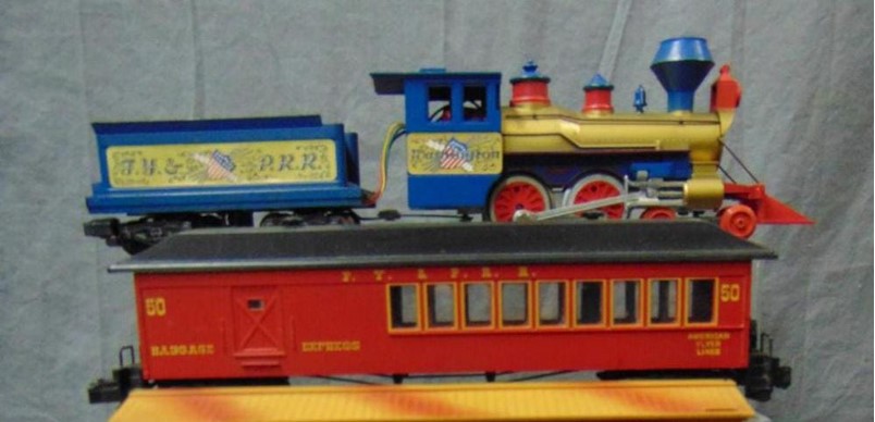
I have to admit I am not an expert on American Flyer variations, but I know some of you out there are! My Washington has the common funnel shaped smoke stack, but certainly the one Joe found is interesting! If anyone has any ideas, email me at myflyertrains@cfl.rr.com and I will forward it to Joe, and perhaps post it here! Thanks!
December 9, 2020
Chat Room!
I would like to remind everyone that the chat room is alive and well, as it has been for over 10 years. The S-Trains chat still takes place on Sunday evenings, but has moved a little later in the evening to 9:30 pm Eastern time, to accommodate people in the western time zones, who are quite active in these chats.
Please join us Sunday at 9:30 pm Eastern, and if you don’t see anyone else right away, hang in there because people will come! The chat software has been updated to the latest version, and has many great new features. You can either log in with your registered username, or just enter any username you wish and gain access to the chatroom right away! Join us Sunday evenings for the S-Trains chat. It is a lot of fun!
The chatroom is open all the time, so you can test it out whenever you wish.
https://www.myflyertrains.net/chat/
See you there! Chuck
————————-
November 18, 2020
Ben Swope has been busy again! See his latest creation in the Ben’s Tracks section.
Thanks Ben for this great constuction article!
Chuck
November 15, 2020
Happy to announce that the All Aboard Sets section has been migrated away from frames and to html / Jalbum. It loads much faster now and is much more usable on your cell phone or tablet.
Thanks for using MyFlyerTrains.Net!
November 10, 2020
MyFlyeTrains.Net now has an SSL certificate. I did this to try and slow these warnings from browsers saying that the website was somehow a security risk to visit. Seems crazy, since we don’t have any credit card processing, or even anything to sign up to, but I caved in. So if you come in to the site by http:// rather than https:// (the secure version), the first time you click a menu you will be taken to the https:// version of the site, and will often see the little padlock in the address bar of your browser. Similarly, if you come in by the MyFlyerTrains.Org or MyFlyerTrains.Com, again the first menu you click on will put you onto the secure SSL https:// site. I hope that people will have less problems with their browsers crying wolf all the time. Some of the links on the site, like in the catalog section are still http:// and it will take me a while to address that.
Thanks for using MyFlyerTrains.Net!
Chuck
November 9, 2020
The chat room has been successfully fully migrated and upgraded to the latest version. All of the user logins along with your avatars are there. My thanks go to Ciprian Murariu, the developer of the chatroom software, for making this happen. It has been an interesting 3 weeks, but the website is pretty much fully migrated and updated! There will be some minor tweaks but the website should stay up from now on! There will now be 3 ways to get to MyFlyerTrains: MyFlyerTrains.Net, MyFlyerTrains.Org, and MyFlyerTrains.com. As always, thanks for using MyFlyerTrains!
November 5, 2020
MyFlyerTrains was hosted by the same company for over 15 years. I will spare you the ugly details, except to say that they are going to be turning off their servers, which forced me to move this website. Much of the content at MyFlyerTrains.org was using old software, that when applied to the new web hosting server, did not work. The problem I faced was huge, and had it not been for the encouragement of Dale Smith of http://americanflyerdisplays.org this day might never have come. Thanks Dale!
Dale suggested a piece of software called Jalbum, and Jalbum now displays the photo album content making it look better than ever. Phones and tablets are now supported, and you can just swipe through the photos on your tablet effortlessly. The new site is also hosted by a well known company that has been around a long time. I plan to pay everything years ahead, so hopefully even if something happens to me, the site will still stay up for a long time.
Deep in the archieves of the old MyFlyerTrains.org I found some real gems that were posted years ago, but long forgotten at least for me. Stumpy Stones kit-bashing articles are wonderful! The photos you photo album owners have uploaded are spectacular!
There has been a price to all this. It has taken me over 100 hours of work to migrate the photo albums to Jalbum. Part of the problem with the old album software (Gallery) was that every time the hosting company updated there MYSQL or PHP, the album broke. The albums are now just plain old HTML. YES, YOUR ALBUMS HAVE BEEN MIGRATED!
But, if you have an album here, you will have to send your new photos to me at email myflyertrains@cfl.rr.com and let me post them for you. Also tell me where you would like them put. Many of you have done this anyway in the past. I am sorry for this inconvenience, but it is just me managing this website, and I do not have my own IT staff. I can not deal with the MYSQL and PHP updates. Also, although in many cases I have copied the original view counts to the photos, these counts will never increment, because of the change away from the “Gallery” software. If you would like an album, let me know, I would be happy to add your train related photos to the website.
My work to update the website will continue, but I believe it has come far enough already, that I can share the new site with all of you.
To all of you that have contributed content to the website of over the years, go my thanks! And as always, thanks for using MyFlyerTrains.org /.net!
Chuck